Zener Diode As Voltage Regulator Part 1

Zener Diode As Voltage Regulator Part 1 Youtube Analog electronics: zener diode as voltage regulator (input voltage & load resistance fixed)topics covered:1. what is voltage regulator.2. zener diode in for. The point at which the zener voltage triggers the current to flow through the diode can be very accurately controlled (to less than 1% tolerance) in the doping stage of the diodes semiconductor construction giving the diode a specific zener breakdown voltage, ( v z ) for example, 4.3v or 7.5v. this zener breakdown voltage on the i v curve is almost a vertical straight line.

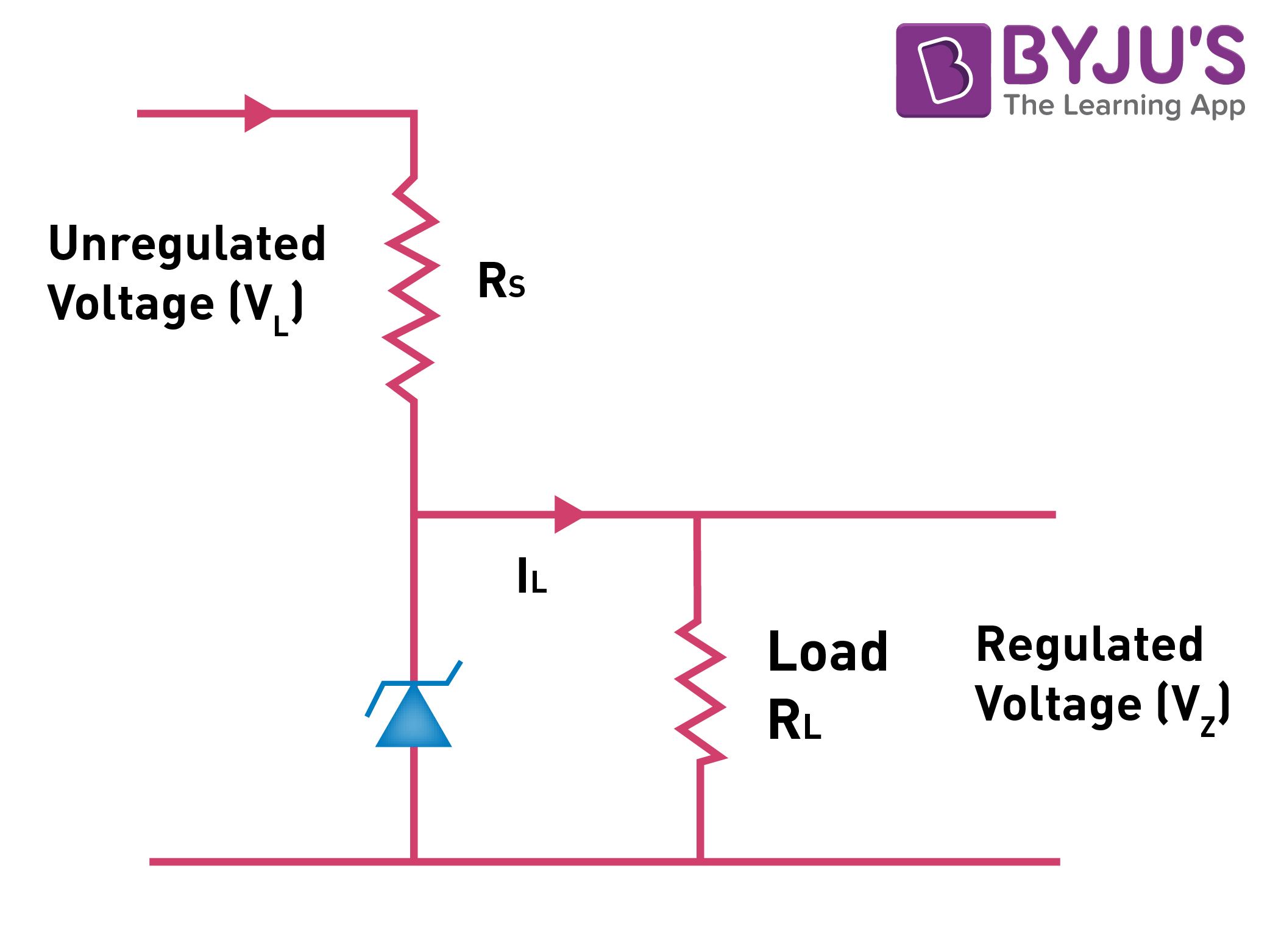
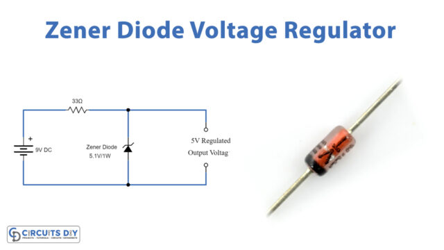
Zener Diode As A Voltage Regulator Working Principles Part 1 of how to use zener diodes. part 1 consists of a demonstration of standard diodes vs zener diodes and how they work to regulate voltage.part 2 here: h. The circuit diagram of a voltage regulator using a zener diode is shown: the value of the series resistor is written as r s = (v l − v z)i l. current through the diode increases when the voltage across the diode tends to increase which results in the voltage drop across the resistor. similarly, the current through the diode decreases when the. A zener diode voltage regulator is made by connecting a zener diode to a resistor in series, with the zener diode in reverse biased mode. the zener diode replaces the second resistor, making this equivalent to a voltage divider. the voltage output is taken across the zener diode, v out = v z: normally, this output is linked across the load, as. 1. first, take note of the zener diode’s rated breakdown voltage or zener voltage. in the datasheet, it is denoted as v z. this parameter specifies the amount of reverse biased voltage that causes the diode to conduct current. for the diode to operate, the voltage applied across the zener diode must be equal or greater than v z.

Zener Diode Voltage Regulator Explanation And How To Build вђ Wira A zener diode voltage regulator is made by connecting a zener diode to a resistor in series, with the zener diode in reverse biased mode. the zener diode replaces the second resistor, making this equivalent to a voltage divider. the voltage output is taken across the zener diode, v out = v z: normally, this output is linked across the load, as. 1. first, take note of the zener diode’s rated breakdown voltage or zener voltage. in the datasheet, it is denoted as v z. this parameter specifies the amount of reverse biased voltage that causes the diode to conduct current. for the diode to operate, the voltage applied across the zener diode must be equal or greater than v z. So zener diodes are intended to function in the reverse breakdown region with a reverse breakdown voltage (vz) in the range 2.4 v to 200 v. the value of vz depends on the doping concentration. when the zener voltage is reached, the zener diode conducts current from its cathode terminal to its anode terminal. Voltage regulation with zener diodes: zener diodes are used as voltage regulators by maintaining a steady voltage across a load, even if input voltage fluctuates. circuit diagram explanation: in a circuit, a zener diode is connected in reverse bias parallel to the load, ensuring the voltage across the load does not exceed the breakdown voltage.

Zener Diode Voltage Regulator Circuit So zener diodes are intended to function in the reverse breakdown region with a reverse breakdown voltage (vz) in the range 2.4 v to 200 v. the value of vz depends on the doping concentration. when the zener voltage is reached, the zener diode conducts current from its cathode terminal to its anode terminal. Voltage regulation with zener diodes: zener diodes are used as voltage regulators by maintaining a steady voltage across a load, even if input voltage fluctuates. circuit diagram explanation: in a circuit, a zener diode is connected in reverse bias parallel to the load, ensuring the voltage across the load does not exceed the breakdown voltage.

Comments are closed.