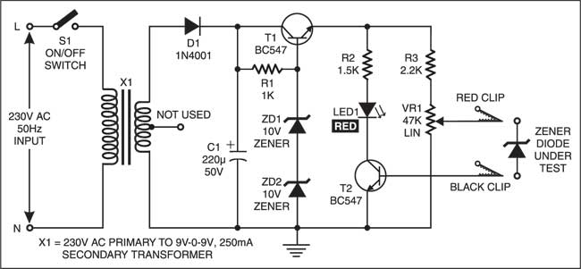
View 19 Schematic Diagram Of Zener Diode

Zener Diode As Voltage Regulator Theory Circuit Diagram Working of zener diode. the zener diode can operate in both forward and reverse bias. in forward bias, it acts as a normal diode with nominal forward voltage drop and a large current flow. while in reverse bias, it blocks current flow until the applied voltage reaches the zener breakdown voltage. this region is known as the zener breakdown. A zener diode is a type of diode that is often used for voltage regulators and shaping waveforms. its symbol is an arrow pointing towards a crooked line. there are actually three different ways you can draw the zener diode symbol in schematics: three ways to draw the zener diode symbol. while a normal diode only allows current to flow through a.

View 19 Schematic Diagram Of Zener Diode The zener diode is used in its “reverse bias” or reverse breakdown mode, i.e. the diodes anode connects to the negative supply. from the i v characteristics curve above, we can see that the zener diode has a region in its reverse bias characteristics of almost a constant negative voltage regardless of the value of the current flowing through the diode. A heavily doped p n junction diode that works in reverse bias conditions is called a zener diode. they are special semiconductor devices that allow the current to flow in both forward and backward directions. for the zener diode, the voltage drop across the diode is always constant irrespective of the applied voltage. Many diodes described as zener diodes rely instead on avalanche breakdown. both types are used with the zener effect predominating under 5.6 v and avalanche breakdown above. regular applications include providing a reference voltage for voltage regulators. this is to protect devices from momentary voltage pulses. The most commonly used zener diode is packaged in a small glass enclosure, with a distinctive band indicating the cathode side of the diode. zener diode symbol and package outlines. the symbol used to represent a zener diode in circuit diagrams is similar to that of a regular diode, but with a unique addition.

Circuit Diagram Zener Diode Characteristics Many diodes described as zener diodes rely instead on avalanche breakdown. both types are used with the zener effect predominating under 5.6 v and avalanche breakdown above. regular applications include providing a reference voltage for voltage regulators. this is to protect devices from momentary voltage pulses. The most commonly used zener diode is packaged in a small glass enclosure, with a distinctive band indicating the cathode side of the diode. zener diode symbol and package outlines. the symbol used to represent a zener diode in circuit diagrams is similar to that of a regular diode, but with a unique addition. Application examples for these components are included. 1. introduction. when biased in the forward direction zener diodes have the same characteristic as a silicon p n diode. most important for zener diode applications is the characteristic when biased in the reverse direction, where zener diodes have a small leakage current below a specific. Zener diode. definition: a heavily doped semiconductor diode which is designed to operate in reverse direction is known as the zener diode. in other words, the diode which is specially designed for optimising the breakdown region is known as the zener diode. the symbolic representation of zener diode is shown in the figure below.

Comments are closed.