Transmission Cooler Installation Diagram 4l60e

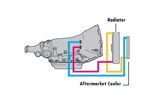
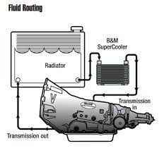
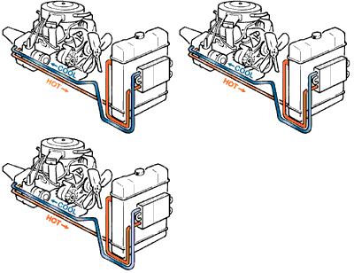
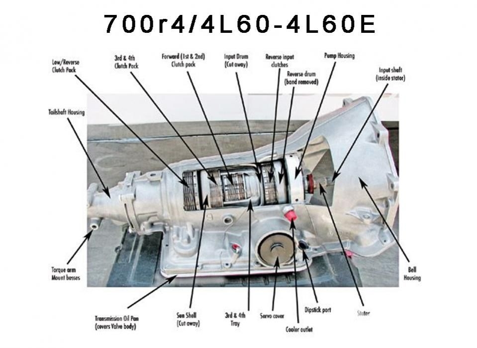
4l60e Transmission Cooler Line Diagram Flow Direction Cpt4l60e When you are finished with the installation, mounting, and plumbing, your transmission cooling diagram will look like this: transmission >feed line >radiator(stock cooler) >aftermarket tranny cooler >return line >transmission it is ideal to splice the transmission cooler into the return line, so that way the coolant flows through the stock in. The 4l60e transmission cooler line flow is very easy to follow. as the gif above shows, the bottom line is the hot line which sends warm transmission fluid out to the factory trans cooler within the radiator at the lower port in most cases. fyi, some vehicles have the factory cooler on the bottom of the radiator, but simply follow the lower.

4l60e Transmission Cooler Line Diagram Flow Direction Cpt4l60e A 4l60e transmission cooler line diagram is a visual representation of the transmission cooling system in a vehicle equipped with a 4l60e transmission. the diagram shows the layout and connections of the coolant lines that are responsible for cooling the transmission fluid. the 4l60e transmission is a popular automatic transmission used in many. How to install remote transmission cooler. i show you how to prolong the life of your transmission by installing a universal transmission cooler. Powered by wordpress and hitmag. view 4l60e transmission cooler line diagrams that route to the radiator and to an external transmission cooler. First, change the transmission filter. even a filter that is slightly clogged will reduce the flow of fluid, resulting in higher friction, and friction builds heat. next, consider changing the smooth transmission pan to a finned automatic transmission pan. by building fins into the pan, you increase the surface area that cool air passes by and.

4l60e Transmission Cooler Line Diagram Flow Direction Cpt4l60e Powered by wordpress and hitmag. view 4l60e transmission cooler line diagrams that route to the radiator and to an external transmission cooler. First, change the transmission filter. even a filter that is slightly clogged will reduce the flow of fluid, resulting in higher friction, and friction builds heat. next, consider changing the smooth transmission pan to a finned automatic transmission pan. by building fins into the pan, you increase the surface area that cool air passes by and. %pdf 1.4 %âãÏÓ 655 0 obj > endobj xref 655 23 0000000016 00000 n 0000001722 00000 n 0000001807 00000 n 0000001941 00000 n 0000002144 00000 n 0000002287 00000 n 0000002673 00000 n 0000002776 00000 n 0000003060 00000 n 0000003479 00000 n 0000003567 00000 n 0000018626 00000 n 0000018910 00000 n 0000019125 00000 n 0000027329 00000 n 0000027585 00000 n 0000143787 00000 n 0000311501 00000 n. Install the cross member and transmission mount. connect all external wiring, hoses, and linkages to the transmission, transfer case, and mount the neutral safety switch and linkage. hang the exhaust loosely. install front and rear drive shafts (match marked). torque the universal joint strap bolts to 27 ft lb.

4l60e Transmission Cooler Lines %pdf 1.4 %âãÏÓ 655 0 obj > endobj xref 655 23 0000000016 00000 n 0000001722 00000 n 0000001807 00000 n 0000001941 00000 n 0000002144 00000 n 0000002287 00000 n 0000002673 00000 n 0000002776 00000 n 0000003060 00000 n 0000003479 00000 n 0000003567 00000 n 0000018626 00000 n 0000018910 00000 n 0000019125 00000 n 0000027329 00000 n 0000027585 00000 n 0000143787 00000 n 0000311501 00000 n. Install the cross member and transmission mount. connect all external wiring, hoses, and linkages to the transmission, transfer case, and mount the neutral safety switch and linkage. hang the exhaust loosely. install front and rear drive shafts (match marked). torque the universal joint strap bolts to 27 ft lb.

4l60e Transmission Cooler Lines Diagram

Comments are closed.