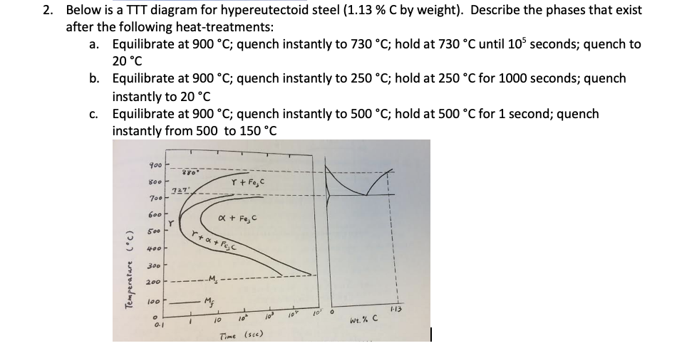
Solved Below Is A Ttt Diagram For Hypereutectoid Steel 1 13 C By
Solved Below Is A Ttt Diagram For Hypereutectoid Steel 1 Chemical engineering questions and answers. below is a ttt diagram for hypereutectoid steel ( 1.13%c by weight). describe the phases that exist after the following heat treatments: a. equilibrate at 900∘c; quench instantly to 730∘c; hold at 730∘c until 105 seconds; quench to 20∘c b. equilibrate at 900∘c; quench instantly to 250∘c. Below is a ttt diagram for hypereutectoid steel (1.13 % c by weight). describe the phases that exist after the following heat treatments: a. equilibrate at 900 °c; quench instantly to 800 °c; hold at 800 °c until reaching equilibrium structure; quench instantly from 800 °c to 20 °c b. equilibrate at 900 °c; quench instantly to 800 °c.
Solved Below Is A Ttt Diagram For Hypereutectoid Steel 1 Time temperature transformation (ttt ) diagram. t (time) t (temperature) t (transformation) diagram is a plot of temperature versus the logarithm of time for a steel alloy of definite composition. it is used to determine when transformations begin and end for an isothermal (constant temperature) heat treatment of a previously austenitized alloy. Salt bath i (fig. 1) is maintained at austenetising temperature (780 ̊c for eutectoid steel). salt bath ii (fig. 2) is maintained at specified temperature at which transformation is to be determined (below ae1), typically 700 250°c for eutectoid steel. bath iii which is a cold water bath is maintained at room temperature. Animated lecture series on heat treatment [complete course]ttt diagram of hypereutectoid steel & its solidification mechanism |lecture 2 |part 4| heat treatm. Mechanical engineering questions and answers. 2. below is a tit diagram for hypereutectoid steel (1.13 % c by weight). describe the phases that exist after the following heat treatments: a. equilibrate at 900 °c; quench instantly to 800 °c; hold at 800 °c until reaching equilibrium structure that is, the relative fractions of each structure.

Solved Below Is A Ttt Diagram For Hypereutectoid Steel Chegg Animated lecture series on heat treatment [complete course]ttt diagram of hypereutectoid steel & its solidification mechanism |lecture 2 |part 4| heat treatm. Mechanical engineering questions and answers. 2. below is a tit diagram for hypereutectoid steel (1.13 % c by weight). describe the phases that exist after the following heat treatments: a. equilibrate at 900 °c; quench instantly to 800 °c; hold at 800 °c until reaching equilibrium structure that is, the relative fractions of each structure. 3.4.1.1 eutectoid transformations. through hardened steels like aisi 52100 are hypereutectic alloys, where the carbon content is greater than 0.77% c by weight. fig. 3.11 shows a representation of the fe c phase diagram along with schematic illustrations of the probable microstructures realized by slowly cooling a hypereutectic fe 1% c alloy. The construction of the ttt diagram involves several steps to accurately represent the transformation kinetics of the steel. step 1: the first step in constructing the ttt diagram is to obtain the experimental data through cooling curve experiments. in these experiments, a small sample of eutectoid steel is heated to a high temperature and then.

Ttt Diagram For Hypereutectoid Steel 3.4.1.1 eutectoid transformations. through hardened steels like aisi 52100 are hypereutectic alloys, where the carbon content is greater than 0.77% c by weight. fig. 3.11 shows a representation of the fe c phase diagram along with schematic illustrations of the probable microstructures realized by slowly cooling a hypereutectic fe 1% c alloy. The construction of the ttt diagram involves several steps to accurately represent the transformation kinetics of the steel. step 1: the first step in constructing the ttt diagram is to obtain the experimental data through cooling curve experiments. in these experiments, a small sample of eutectoid steel is heated to a high temperature and then.

Comments are closed.