Series Rlc Resonant Circuit Ac Circuits Basics Electronics

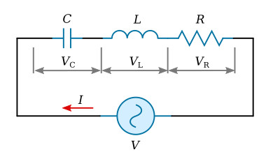
Series Rlc Resonant Circuit Ac Circuits Basics Electronics In complex form, the resonant frequency is the frequency at which the total impedance of a series rlc circuit becomes purely “real”, that is no imaginary impedance’s exist. this is because at resonance they are cancelled out. so the total impedance of the series circuit becomes just the value of the resistance and therefore: z = r. Series rlc circuit example no1. a series rlc circuit containing a resistance of 12Ω, an inductance of 0.15h and a capacitor of 100uf are connected in series across a 100v, 50hz supply. calculate the total circuit impedance, the circuits current, power factor and draw the voltage phasor diagram. inductive reactance, xl. capacitive reactance, xc.

Series Resonance In A Series Rlc Resonant Circuit Electrical Aca The above equation can be used to determine the resonant frequency if the elements of the series circuit are known. this is demonstrated in example 1. example 1: the elements in the circuit of figure above are: l = 8 mh, c = 0.5 nf, r = 500 Ω, and v = 300∠0° v. find (1) the resonant frequency, (2) the current, and (3) the voltage across. The lc circuit. in the limit r →0 the rlc circuit reduces to the lossless lc circuit shown on figure 3. s c l vc vl figure 3 the equation that describes the response of this circuit is 2 2 1 0 dvc vc dt lc = (1.16) assuming a solution of the form aest the characteristic equation is s220 ωο = (1.17) where 1 ο lc ω= the two roots are. Figure 23.3.2: this graph shows the relationships of the voltages in an rlc circuit to the current. the voltages across the circuit elements add to equal the voltage of the source, which is seen to be out of phase with the current. an rlc series circuit has a 40.0Ω resistor, a 3.00 mh inductor, and a 5.00μf capacitor. The resonant frequency for a rlc circuit is calculated from equation 15.6.5, which comes from a balance between the reactances of the capacitor and the inductor. since the circuit is at resonance, the impedance is equal to the resistor. then, the peak current is calculated by the voltage divided by the resistance. solution.

Comments are closed.