Pin On Ide

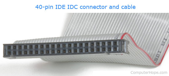
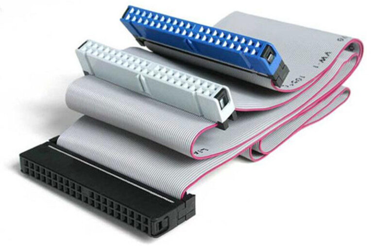
What Is Ide Advanced technology attachment (ata), is a standard interface for connecting storage devices such as hard disks and cd rom drives inside personal computers. nowdays superseeded by sata (see sata pinout). ata standards allow cable lengths in the range of 450 to 900 mm, so the technology normally appears as an internal computer storage interface. While the pin designations remain the same as with regular ide cables, at ultra ata 66 speeds signal quality issues become a major concern. it is due to this fact that your system needs to determine if you are using the newer 80 pin cable, or older 40 pin cable, before it will enable ultra ata 66 mode.

Ide Full Form What Is The Full Form Of Ide Learn Dunia Debugging the stm32 over arduino's ide. to start a debug session in the arduino’s ide, click on tools > upload method > “serial wire debug” option, as follows: after that, click on the “verify” symbol to compile the code and then on the “start debugging” button. the perspective changes to the debug perspective, as follows:. The esp32 has two i2c channels and any pin can be set as sda or scl. when using the esp32 with the arduino ide, the default i2c pins are: gpio 21 (sda) gpio 22 (scl) if you want to use other pins when using the wire library, you just need to call: wire.begin(sda, scl);. Change pin configuration. to change the pin configuration, open the arduino ide, and navigate to tools > pin numbering. here you can select between the default (nano) and legacy (esp32) options. change pin configuration in the arduino ide. you can now upload a sketch, and the configuration will change. nano esp32 pin map. Example code for blinking inbuilt led of nodemcu. 1 void setup() { 2 initialize inbuilt led pin as an output. 3 pinmode(led builtin, output); 4} 5 6 loop function runs over and over again forever 7 void loop() { 8 digitalwrite(led builtin, high); turn the led on by making the pin 13 high 9 delay(500); wait for a 0.5 second 10.

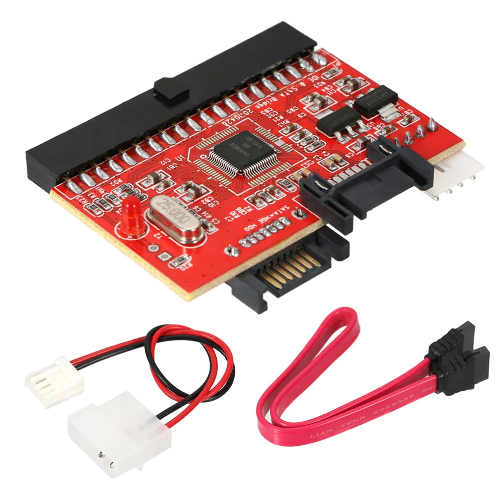
2 In 1 Ide To Sata Sata To Ide Adapter Converter 4 Pin Power Connector Change pin configuration. to change the pin configuration, open the arduino ide, and navigate to tools > pin numbering. here you can select between the default (nano) and legacy (esp32) options. change pin configuration in the arduino ide. you can now upload a sketch, and the configuration will change. nano esp32 pin map. Example code for blinking inbuilt led of nodemcu. 1 void setup() { 2 initialize inbuilt led pin as an output. 3 pinmode(led builtin, output); 4} 5 6 loop function runs over and over again forever 7 void loop() { 8 digitalwrite(led builtin, high); turn the led on by making the pin 13 high 9 delay(500); wait for a 0.5 second 10. Esp32 control digital outputs. first, you need set the gpio you want to control as an output. use the pinmode () function as follows: pinmode(gpio, output); to control a digital output you just need to use the digitalwrite () function, that accepts as arguments, the gpio (int number) you are referring to, and the state, either high or low. This article is a guide for the esp8266 gpios: pinout diagrams, their functions and how to use them. the esp8266 12 e chip comes with 17 gpio pins. not all gpios are exposed in all esp8266 development boards, some gpios are not recommended to use, and others have very specific functions. with this guide, you’ll learn how to properly use the.

Comments are closed.