How Do Zener Diodes Work In A Circuit Wiring Diagram

How Do Zener Diodes Work In A Circuit Wiring Diagram A zener diode is a type of diode that is often used for voltage regulators and shaping waveforms. its symbol is an arrow pointing towards a crooked line. there are actually three different ways you can draw the zener diode symbol in schematics: three ways to draw the zener diode symbol. while a normal diode only allows current to flow through a. A zener diode is a silicon pn junction device that allows current to flow not only in the forward direction like a typical silicon or germanium diode, but also in the reverse direction if the voltage is greater than the breakdown voltage known as zener knee voltage or simply zener voltage, named after clarence melvin zener, the discoverer of this electrical property.

What Is Zener Diode Its Principle Working And Example Usage The zener diode is used in its “reverse bias” or reverse breakdown mode, i.e. the diodes anode connects to the negative supply. from the i v characteristics curve above, we can see that the zener diode has a region in its reverse bias characteristics of almost a constant negative voltage regardless of the value of the current flowing through the diode. Working of zener diode. the zener diode can operate in both forward and reverse bias. in forward bias, it acts as a normal diode with nominal forward voltage drop and a large current flow. while in reverse bias, it blocks current flow until the applied voltage reaches the zener breakdown voltage. this region is known as the zener breakdown. The most commonly used zener diode is packaged in a small glass enclosure, with a distinctive band indicating the cathode side of the diode. zener diode symbol and package outlines. the symbol used to represent a zener diode in circuit diagrams is similar to that of a regular diode, but with a unique addition. Working principle of zener diode. whenever a pn junction diode is reverse biased, the depletion layer results in being wider. in case this kind of reverse biased voltage throughout the diode is raised consistently, the depletion layer will become a lot more larger. simultaneously, you will see continuous reverse saturation current as a result.

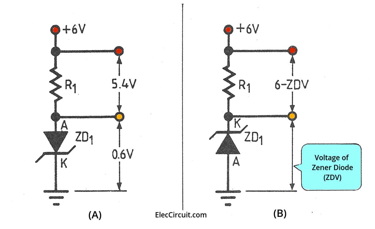
How Is A Zener Diode Connected Into Circuit Wiring Diagram The most commonly used zener diode is packaged in a small glass enclosure, with a distinctive band indicating the cathode side of the diode. zener diode symbol and package outlines. the symbol used to represent a zener diode in circuit diagrams is similar to that of a regular diode, but with a unique addition. Working principle of zener diode. whenever a pn junction diode is reverse biased, the depletion layer results in being wider. in case this kind of reverse biased voltage throughout the diode is raised consistently, the depletion layer will become a lot more larger. simultaneously, you will see continuous reverse saturation current as a result. Zener diode regulator circuit, zener voltage = 12.6v). zener diode operation please take note of the zener diode’s orientation in the above circuit: the diode is reverse biased, and intentionally so. if we had oriented the diode in the “normal” way, so as to be forward biased, it would only drop 0.7 volts, just like a regular rectifying. A diode is a semiconductor device which conducts in a single direction (unidirectional). zener diodes are also semiconductor devices, but the key difference is that they conduct in both a forward and reverse bias condition. another important difference between the two types is doping intensity. conventional diodes are typically moderately doped.

Zener Diode Voltage Regulator Explanation And How To Build вђ Wira Zener diode regulator circuit, zener voltage = 12.6v). zener diode operation please take note of the zener diode’s orientation in the above circuit: the diode is reverse biased, and intentionally so. if we had oriented the diode in the “normal” way, so as to be forward biased, it would only drop 0.7 volts, just like a regular rectifying. A diode is a semiconductor device which conducts in a single direction (unidirectional). zener diodes are also semiconductor devices, but the key difference is that they conduct in both a forward and reverse bias condition. another important difference between the two types is doping intensity. conventional diodes are typically moderately doped.

Comments are closed.