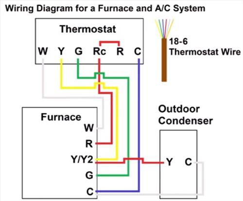
Heat And Cool Thermostat Wiring Diagram

Thermostat Wiring Explained R or rc wire (power) connected to the r power terminal to power the thermostat. w wire (heat), connected to the heating control. g wire (fan) connected to the fan control to operate a blower in your hvac system. y1 wire (cooling) connected to the y terminal compressor refrigerant system. Here’s how to wire a thermostat using the color code and, fyi, each terminal’s purpose. attach the red wire to the r terminal (call for heating and or cooling). attach the green wire to the g terminal (fan). attach the white wire to the w terminal (heat). attach the yellow wire to the y terminal (ac).

Cync Thermostat Wiring Configuration And Installation Guide White wire: heating. blue wire: cooling. rh: heating power. rc: cooling power. to reconnect the wire, simply put the wire on the right terminal and tighten down the set screw. pull a wire a bit to make sure the wire is properly fixed. example: reconnect the red wire to r, tighten the screw, check, and move to the new wire. The 4 wire thermostat wiring is typically found in heat pumps or hvac devices that can heat and cool. the 4 wire thermostat color code includes a red wire that works for power (24v), a white wire—connected to a “w” or ”w1” terminal—that works for heating, a green wire that works for fan, and a yellow or sky blue wire—connected to. If you have a c wire, place it into the c terminal on your wall plate. c wire adapters are available here. let’s look at the g wire. this wire goes to the g terminal on your new thermostat. of the y, y1, and y2 wires, y or y1 go to the y terminal and y2 to the y2 terminal. the o b wire can have many configurations. Disconnect the wires. once you’ve located all the wires, taken a photo, and labeled where everything goes, it’s time to disconnect the wires and the mounting screws. make sure to tape the wires down so they don’t fall inside the wall. remove any anchor screws and the backplate of the existing thermostat.

Thermostat Wiring Explained If you have a c wire, place it into the c terminal on your wall plate. c wire adapters are available here. let’s look at the g wire. this wire goes to the g terminal on your new thermostat. of the y, y1, and y2 wires, y or y1 go to the y terminal and y2 to the y2 terminal. the o b wire can have many configurations. Disconnect the wires. once you’ve located all the wires, taken a photo, and labeled where everything goes, it’s time to disconnect the wires and the mounting screws. make sure to tape the wires down so they don’t fall inside the wall. remove any anchor screws and the backplate of the existing thermostat. Y or y1: yellow thermostat wire. in traditional cooling systems, the yellow wire controls the cooling function. in a heat pump, it controls the compressor, which can both heat and cool your home. the yellow wire is connected to the y or y1 terminal on your thermostat. in a multi stage cooling system, this serves as the first stage. The hvac wiring diagram thermostat illustrates the electrical connections between the thermostat, the heating or cooling system, and the power supply. it shows the different wires and terminals involved in the system and their corresponding functions. the diagram provides a visual representation of how the thermostat interacts with the hvac.

Heating And Ac Thermostat Wiring Y or y1: yellow thermostat wire. in traditional cooling systems, the yellow wire controls the cooling function. in a heat pump, it controls the compressor, which can both heat and cool your home. the yellow wire is connected to the y or y1 terminal on your thermostat. in a multi stage cooling system, this serves as the first stage. The hvac wiring diagram thermostat illustrates the electrical connections between the thermostat, the heating or cooling system, and the power supply. it shows the different wires and terminals involved in the system and their corresponding functions. the diagram provides a visual representation of how the thermostat interacts with the hvac.

Simple Thermostat Wiring Guide 2 3 4 5 6 7 8 Wires Color Code

Comments are closed.