Circuit Diagram Of Zener Diode

Zener Diode Circuit Diagram For Voltage Regulation Etechnog Learn about zener diodes, semiconductor devices that can conduct current in both directions. find out how they work, their circuit symbol, their v i characteristics, and their applications. A zener diode is always operated in its reverse biased condition. as such a simple voltage regulator circuit can be designed using a zener diode to maintain a constant dc output voltage across the load in spite of variations in the input voltage or changes in the load current. the zener voltage regulator consists of a current limiting resistor.

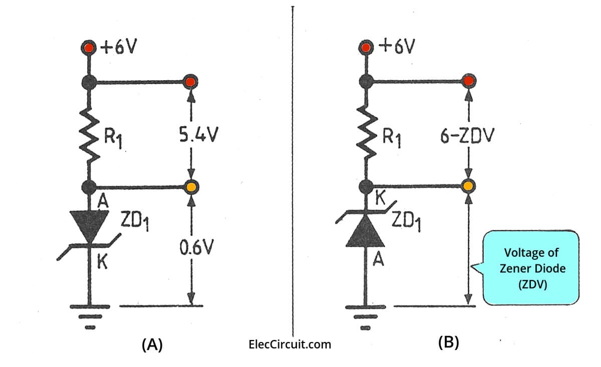
What Is Zener Diode Its Principle Working And Example Usage A zener diode is a type of diode that is often used for voltage regulators and shaping waveforms. its symbol is an arrow pointing towards a crooked line. there are actually three different ways you can draw the zener diode symbol in schematics: three ways to draw the zener diode symbol. while a normal diode only allows current to flow through a. Working of zener diode. the zener diode can operate in both forward and reverse bias. in forward bias, it acts as a normal diode with nominal forward voltage drop and a large current flow. while in reverse bias, it blocks current flow until the applied voltage reaches the zener breakdown voltage. this region is known as the zener breakdown. The figure given below is the circuit diagram of the zener diode. the zener diode has applications in various electronic devices and it works in reverse biasing conditions. in reverse biasing, the p type material of the diode is connected with the negative terminal of the power supply, and the n type material is connected with the positive. Zener diode regulator circuit, zener voltage = 12.6v). zener diode operation please take note of the zener diode’s orientation in the above circuit: the diode is reverse biased, and intentionally so. if we had oriented the diode in the “normal” way, so as to be forward biased, it would only drop 0.7 volts, just like a regular rectifying.

Comments are closed.