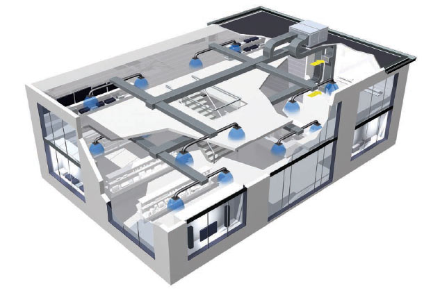
Central Hvac Rooftop Plant System Architecture Diagram Diagram

Central Hvac Rooftop Plant System Architecture Diagram Diagram The latest addition to the skyline of västerås city will be a high rise building that features three dimensional facades and an unprecedented panoramic garden o. Updated on july 24th, 2024. hvac drawings and blueprints are essential for construction projects, to ensure alignment with design and compliance with codes, facilitate precise installations, reduce errors, and ease future maintenance. digitalization, bim, iot, and ai driven predictive maintenance enable sustainable and eco friendly hvac.

Rooftop Hvac Unit Diagram Hvac drawingscontent1. reading hvac drawings 2. hvac plans 3. skip to quiz! reading hvac drawingsthe mechanical drawings consist of the hvac (heating, ventilating, and air conditioning) systems. the details of a complete hvac system are provided in hvac plans. this is a very important part of hvac training. let’s see the details provided at different locations of drawings. recall that the. Central plants are the heart of the hvac systems in large buildings or complexes of buildings. this section provides information on boilers, chillers, cooling towers, energy storage, pumps, water treatment systems, valves, pipes, sensors, and controls. typically, central plants supply systems with cooling loads in excess of 50 tons. the added. An hvac plan in a house is designed to provide year round comfort and healthy indoor air quality. the system may consist of a central unit or separate units for heating and cooling, air filters for improved air quality, and ventilation systems to circulate fresh air throughout the home. the design of the hvac plan may vary depending on the size. Easy collaboration. smartdraw makes it easy to work with a team on any hvac design project. you can save your hvac drawing to a shared folder and work on it together. your team or client can easily add comments and feedback. smartdraw also works where you already communicate with your team. you can collaborate on hvac designs in microsoft teams.

Commercial Building Hvac System Diagrams An hvac plan in a house is designed to provide year round comfort and healthy indoor air quality. the system may consist of a central unit or separate units for heating and cooling, air filters for improved air quality, and ventilation systems to circulate fresh air throughout the home. the design of the hvac plan may vary depending on the size. Easy collaboration. smartdraw makes it easy to work with a team on any hvac design project. you can save your hvac drawing to a shared folder and work on it together. your team or client can easily add comments and feedback. smartdraw also works where you already communicate with your team. you can collaborate on hvac designs in microsoft teams. Ladder, line, and installation schematics. hvac system diagrams and schematics fall into three different categories: ladder, line, and installation diagrams. here’s how those break down. ladder diagrams. the ladder diagram is one of the easier ones to read. it lists the circuit connections and electrical wiring for the system. Good hvac systems use the science of thermodynamics, heat transfer, and fluid mechanics to work. these are all fancy terms that mean the system will make the air warmer or cooler, creating a constant temperature inside your home. the science of cooling air means more than just blowing more air around and creating a current.

Comments are closed.