Carrier Bus Air Conditioning Wiring Diagram

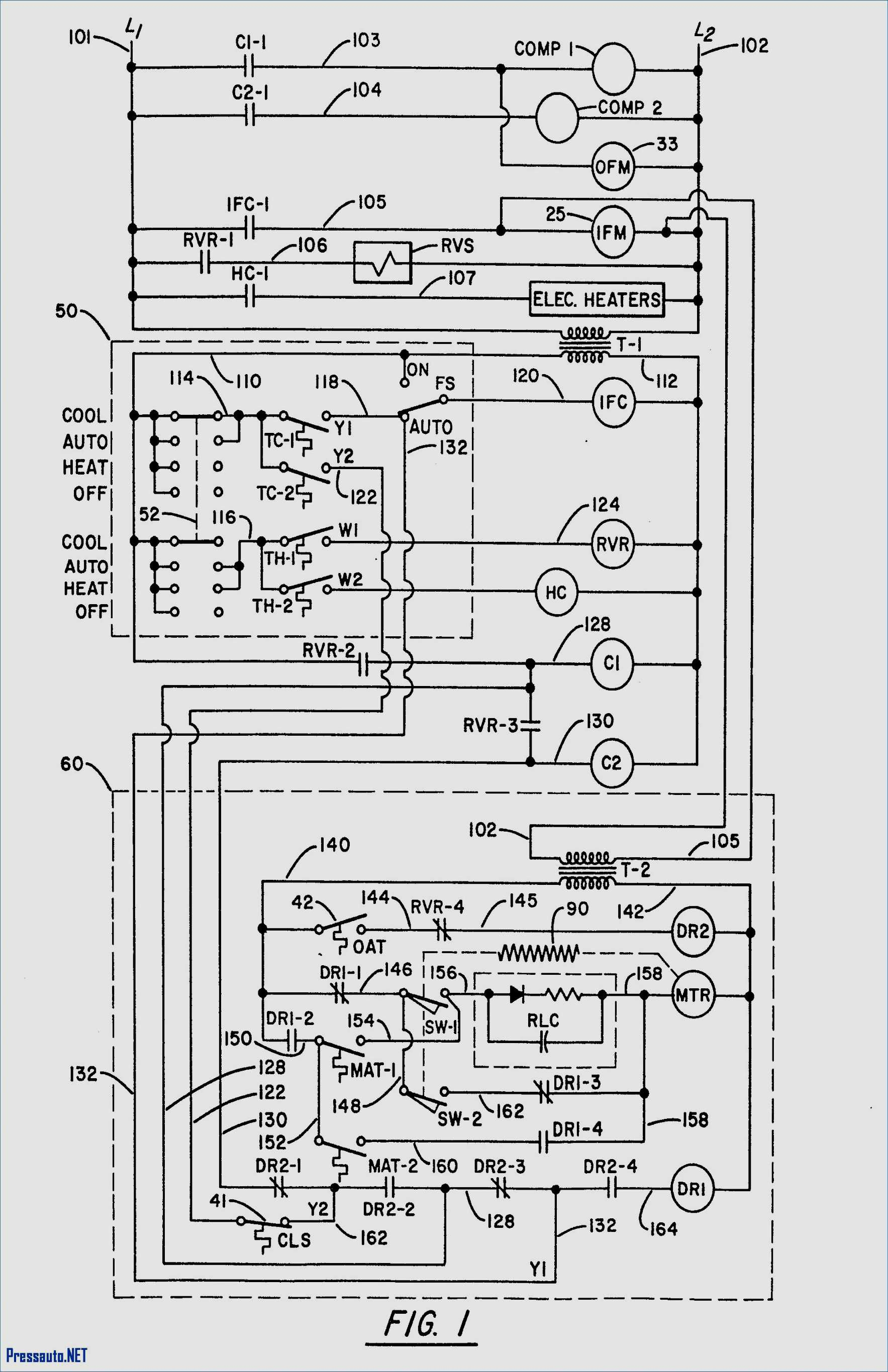
Carrier Bus Air Conditioning Wiring Diagram Let our 20 years of bus ac experience help you find the correct solution for your needs and budget. carrier 98 63163 wiring diagram trans air wiring diagram. The diagrams show which wires go from the control panel to the motors, blowers, and other components, providing detailed information about how each part of your system works together. every time air conditioning systems are serviced, they must be rewired according to the diagrams. having access to correct and up to date carrier bus air.

Carrier Ac Schematics To find the dealer nearest you, go to transportaircon.carrier and click on “dealer locator”, or refer to the carrier bus stop dealer directory (62 10810) or contact the carrier transport air conditioning technical service hot line 1 (800) 450 2211. Carrier 98 (67037,63176,63135) wiring diagrams. ac 430, 12v. transarctic sells and supports carrier ac systems for buses. let our 20 years of bus ac experience help you find the correct solution for your needs and budget. Motormaster control to be wired directly to ccb cir cuit breaker and the ofc1 contactor should be removed from the wiring. connect start relay fr to the following terminals: 230 3 60 tb1 tb2 460 3 60 tb1 tb2 575 3 60 tb1 tb2 208 3 60 tb13a tb2. add fr relay in parallel with ofc1 (see fig. 8). The em 23 is an after market heating cooling unit normally installed in the vehicle dash. for installation instructions and or information on these type systems contact the carrier transport air conditioning technical figure 2 59 iw 1 secured to structure rail tbb service hot line (1 800 450 2211).
Carrier Bus Air Conditioning Wiring Diagram Motormaster control to be wired directly to ccb cir cuit breaker and the ofc1 contactor should be removed from the wiring. connect start relay fr to the following terminals: 230 3 60 tb1 tb2 460 3 60 tb1 tb2 575 3 60 tb1 tb2 208 3 60 tb13a tb2. add fr relay in parallel with ofc1 (see fig. 8). The em 23 is an after market heating cooling unit normally installed in the vehicle dash. for installation instructions and or information on these type systems contact the carrier transport air conditioning technical figure 2 59 iw 1 secured to structure rail tbb service hot line (1 800 450 2211). Remove refrigerant using a refrigerant recovery sys 4.8.3 adding partial charge tem. a. install manifold gauge set at the compressor suction service valve and service port above the discharge h. start vacuum pump and open all valves. dehydrate line check valve. see figure figure 4 6. unit to 500 microns hg vacuum. Support documents. trans air’s desire is to make this website as useful as possible for any type of customer. if for any reason you are unable to find the document you require, please feel free to contact us for personalized assistance. note: electrical and piping diagrams published here are listed by trans air drawing number (part number).

Carrier Bus Air Conditioning Wiring Diagram Remove refrigerant using a refrigerant recovery sys 4.8.3 adding partial charge tem. a. install manifold gauge set at the compressor suction service valve and service port above the discharge h. start vacuum pump and open all valves. dehydrate line check valve. see figure figure 4 6. unit to 500 microns hg vacuum. Support documents. trans air’s desire is to make this website as useful as possible for any type of customer. if for any reason you are unable to find the document you require, please feel free to contact us for personalized assistance. note: electrical and piping diagrams published here are listed by trans air drawing number (part number).

Comments are closed.