Ac Series Circuit Impedance Diagram

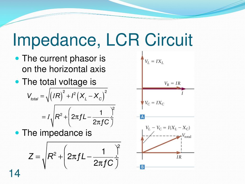
Ac Series Circuit Impedance Diagram In both cases this voltage current ( v i ) relationship is always linear in a pure resistance. so when using resistors in ac circuits the term impedance, symbol z is the generally used to mean its resistance. therefore, we can correctly say that for a resistor, dc resistance = ac impedance , or r = z. the impedance vector is represented by the. Series rlc circuit example no1. a series rlc circuit containing a resistance of 12Ω, an inductance of 0.15h and a capacitor of 100uf are connected in series across a 100v, 50hz supply. calculate the total circuit impedance, the circuits current, power factor and draw the voltage phasor diagram. inductive reactance, xl. capacitive reactance, xc.

Ac Series Circuit Impedance Diagram 12.2 simple ac circuits before examining the driven rlc circuit, let’s first consider the simple cases where only one circuit element (a resistor, an inductor or a capacitor) is connected to a sinusoidal voltage source. 12.2.1 purely resistive load consider a purely resistive circuit with a resistor connected to an ac generator, as shown. Impedance and complex impedance. in an alternating current, known commonly as an “ac circuit”, impedance is the opposition to current flowing around the circuit. impedance is a value given in ohms that is the combined effect of the circuits current limiting components within it, such as resistance (r), inductance (l), and capacitance (c). Figure 23.3.1: an rlc series circuit with an ac voltage source. the combined effect of resistance r, inductive reactance xl, and capacitive reactance xc is defined to be impedance, an ac analogue to resistance in a dc circuit. current, voltage, and impedance in an rlc circuit are related by an ac version of ohm’s law:. Performed on a calculator (preserving all digits), the answer you will receive should be exactly 120 j0 volts. we can also use spice to verify our figures for this circuit: example series r, l, and c spice circuit. l1 2 3 650m. c1 3 0 1.5u. .ac lin 1 60 60. .print ac v(1,2) v(2,3) v(3,0) i(v1).

Ac Series Circuit Impedance Diagram Figure 23.3.1: an rlc series circuit with an ac voltage source. the combined effect of resistance r, inductive reactance xl, and capacitive reactance xc is defined to be impedance, an ac analogue to resistance in a dc circuit. current, voltage, and impedance in an rlc circuit are related by an ac version of ohm’s law:. Performed on a calculator (preserving all digits), the answer you will receive should be exactly 120 j0 volts. we can also use spice to verify our figures for this circuit: example series r, l, and c spice circuit. l1 2 3 650m. c1 3 0 1.5u. .ac lin 1 60 60. .print ac v(1,2) v(2,3) v(3,0) i(v1). Figure 2.3.1: circuit for example 2.3.1. first we need to find the capacitive reactance value. xc = − j 1 2πfc. xc = − j 1 2π15khz910pf. xc = − j11.66kΩ. as there is only one resistor and one capacitor, the result in rectangular form is 47k − j11.66kΩ. in polar form this is: magnitude = √real2 imaginary2. Example 15.4.1: an rlc series circuit. the output of an ac generator connected to an rlc series combination has a frequency of 200 hz and an amplitude of 0.100 v. if r = 4.00Ω, l = 3.00 × 10 − 3h, and c = 8.00 × 10 − 4f, what are (a) the capacitive reactance, (b) the inductive reactance, (c) the impedance, (d) the current amplitude, and.

Comments are closed.